
Green Energy and Sustainability ISSN 2771-1641
Green Energy and Sustainability 2026;6(2):0006 | https://doi.org/10.47248/ges2606020006
Original Research Open Access
Liquid hydrogen fuel system design for sustainable aviation applications
Vasilis Karaiskos
1
 ,
Konstantinos Fotis
1,2
,
Zinon Vlahostergios
1,2
,
Dimitrios Misirlis
1,3
,
Kyros Yakinthos
1
,
Konstantinos Fotis
1,2
,
Zinon Vlahostergios
1,2
,
Dimitrios Misirlis
1,3
,
Kyros Yakinthos
1
Correspondence: Vasilis Karaiskos
Academic Editor(s): Tony Roskilly, Georgios Martinopoulos, Georgia Kastrinaki, Hande Eryilmaz, Martin Roeb
Received: Oct 31, 2025 | Accepted: Apr 28, 2026 | Published: May 20, 2026
This article belongs to the Special Issue Selected Papers from the Conference ICRES 2025
© 2026 by the author(s). This is an Open Access article distributed under the Creative Commons License Attribution 4.0 International (CC BY 4.0) license, which permits unrestricted use, distribution and reproduction in any medium or format, provided the original work is correctly credited.
Cite this article: Karaiskos V, Fotis K, Vlahostergios Z, Misirlis D, Yakinthos K. Liquid hydrogen fuel system design for sustainable aviation applications. Green Energy Sustain. 2026;6(2):0006. https://doi.org/10.47248/ges2606020006
The growing interest in sustainable aviation has highlighted liquid hydrogen (LH2) as a promising alternative to conventional fuels. This study develops a systems level, conceptual approach to size and assess the key elements of an LH2 fuel system for a short-range commercial aircraft with operational and geometric characteristics similar to those of the Airbus A220-300. A configuration with two fuselage mounted tanks (front and aft), providing a total fuel capacity of approximately 4 t of LH2, is considered. A modeling framework is developed by coupling a tank sizing model with a one-dimensional distribution system model to evaluate key physical phenomena influencing system performance, including pressure losses, thermal behavior and overall weight impact, along the fuel path from the storage tanks to the engine interfaces under steady operating conditions. The architecture reflects typical safety and redundancy requirements for hydrogen systems, while remaining sufficiently simple to serve as a preliminary, low fidelity sizing tool at conceptual design level. The predicted fuel system mass is compared against several empirical mass correlations from the literature, providing an initial consistency check for the modelled architecture. The resulting framework provides a structured, low fidelity methodology for assessing LH2 storage and main distribution architectures and for identifying key design drivers and tradeoffs relevant to aircraft level integration.
Keywordshydrogen fuel, aviation, sustainable aviation, fuel distribution system, aerospace engineering, liquid hydrogen, cryogenic systems
The aviation industry is under increasing pressure to reduce its environmental impact, as commercial air transport contributes an estimated 2–3% of global CO2 emissions [1]. Meeting international climate targets requires the adoption of alternative propulsion concepts and cleaner fuels capable of delivering substantial reductions in greenhouse gas emissions. Among the potential solutions, liquid hydrogen is considered one of the most promising due to its high gravimetric energy density, absence of carbon emissions during combustion, and compatibility with advanced propulsion technologies [2].
Hydrogen combustion characteristics provide additional advantages. The high adiabatic flame temperature achievable with hydrogen can enhance thermodynamic efficiency in gas turbine cycles. Its wide flammability limits, rapid diffusivity, and efficient mixing enable the use of compact combustors, which can help reduce NO× formation. Furthermore, its specific heat capacity, which is greater than that of kerosene, offers opportunities for advanced thermal management strategies, such as intercooling and recuperation, that may improve engine efficiency and reduce specific fuel consumption [3].
Despite these benefits, the implementation of hydrogen in aviation presents several technical challenges. A key limitation is hydrogen’s low volumetric energy density: at standard conditions, 1 kg of hydrogen occupies approximately 12m3, making storage in gaseous form impractical. Consequently, cryogenic storage at around 20 K is required to reduce the fuel’s volume to usable levels. This necessitates robust, insulated tanks and pipelines made from materials capable of maintaining mechanical strength at cryogenic temperatures, such as stainless steel SS 304 and aluminum alloy Al 2219. Effective insulation, typically polyurethane or rigid foams, is also required to minimize heat ingress and control boil-off during storage and operation [1,4].
The integration of LH2 fuel systems into aircraft requires a holistic design approach that accounts not only for tanks and pipelines but also for subsystems such as refueling, defueling, pressurization, and venting. Ensuring redundancy and compliance with safety standards, such as those of the Federal Aviation Administration (FAA) [5], is equally important to guarantee operational reliability. Furthermore, the influence of LH2 systems on aircraft configuration, weight distribution, and maintenance requirements highlights the importance of assessing fuel systems within the broader context of aircraft level integration [6].
This work contributes a practical methodology for early stage LH2 fuel system assessment by coupling two complementary models. A tank sizing model is used to determine tank geometry, structural sizing and boil-off-rate (BOR) driven insulation thickness, and a one-dimensional distribution model is used to estimate pressure losses, heat ingress and component masses along the main feed path from the tank outlets to the engine-mounted high pressure pump inlet. Tank model outputs provide the boundary conditions for the distribution analysis. The coupled workflow provides a consistent basis for preliminary architecture trade studies and identification of key mass drivers, while detailed modeling of supporting subsystems and transient operation is left for future work. The calculated fuel system mass is compared with empirical correlations from the literature as an initial consistency check.
The present study focuses on the development and evaluation of a liquid hydrogen fuel system for a short-range aircraft, using a configuration with operational and geometric characteristics similar to those of the A220-300 class. The work includes quantifying component masses and estimating the overall fuel-system mass. The analysis is conducted for a total LH2 capacity of approximately 4 t, which serves as the reference case for sizing the storage and distribution system. The modeling approach includes the design methodology for both the storage tanks and the overall fuel distribution system, aiming to ensure safe, efficient and reliable fuel delivery under cryogenic conditions while satisfying the operational requirements of the selected aircraft class.
The analysis is performed by coupling two complementary models. First, a tank sizing tool is used to define the reference LH2 storage tanks (geometry, structural thickness and insulation level) and to estimate steady heat leakage and boil-off rate (BOR) under specified ambient conditions. Second, a one-dimensional (1D) hydrogen distribution model is used to compute pressure losses, heat leakage and component masses along the feed path from the tank outlets to the inlet of the engine-mounted high pressure pump. The tank model provides the boundary conditions for the distribution model, namely tank outlet pressure and temperature, tank geometry constraints, and the insulation level (or BOR target) adopted for the storage system.
To assess the impact of the hydrogen fuel system on aircraft integration, a representative model of the fuselage-mounted fuel tanks is developed.
The modeling approach includes geometric sizing of the inner volume to store the required hydrogen mass based on mission energy demands and fuselage constraints, mechanical analysis to determine the minimum allowable inner wall thickness, and thermal modeling to evaluate insulation performance and minimize heat ingress.
By design, the two front-and-aft tank configuration provides redundant fuel supply capability and is therefore adopted in this study in preference to a single tank arrangement. Feeding both engines from one tank would introduce a single point of failure, potentially affecting both engines simultaneously. In addition, the ability to transfer fuel between tanks in flight can help mitigate constraints on the flight envelope.
A non-integral tank concept is adopted, structurally decoupled from the primary airframe; the tank therefore carries only its own weight, that of the contained fuel and the internal pressure loads, but not the primary airframe loads. This approach is selected as a more straightforward and less complex solution, which is more suitable given that the focus of this study lies on robustness.
Each tank is modelled as a cylinder with semi-spherical caps. The inner volume is sized so that the required hydrogen mass for the design mission can be stored as saturated liquid at 20 K with a small gaseous volume fraction fixed at 3 %, i.e. the liquid volume fraction is limited to 97 %. This choice provides sufficient headspace for venting and pressure control while maximizing usable liquid volume [7]. The corresponding average fluid density is approximately 71 kg·m-3.
In line with established safety and operational guidelines, the minimum tank pressure is set to 1.2 bar, slightly above the maximum expected ambient pressure, to avoid air ingress. For the steady-state sizing point considered in this study, the tank pressure is assumed to be constant at 1.6 bar [8].
The minimum internal wall thickness is calculated by:
where
Heat transfer from the compartment to the LH2 occurs through three mechanisms: natural convection and radiation at the external tank surface, radial conduction through the insulation, and natural convection at the internal tank surface. To assess the performance of the insulation and quantify these effects, a detailed thermal model is developed and represented as a series of thermal resistances in an electrical analogy network as illustrated in Figure 1 below:

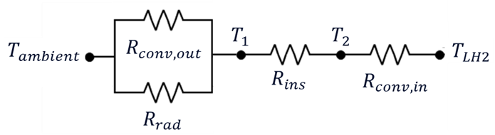
Figure 1. Thermal resistance circuit for heat flow through the tank.
The driving dimensionless groups for natural convection are the Grashof and Rayleigh numbers defined as:
where g is the gravitational acceleration,
The corresponding convective heat transfer coefficient is then:
where
In addition to convection, thermal radiation from the surroundings is included through an equivalent radiative coefficient:
where
The total external heat transfer coefficient is therefore:
and the corresponding external thermal resistance is:
with
Selecting an appropriate insulation system is crucial for the effectiveness of a cryogenic storage system, as it must mitigate pressure fluctuations caused by environmental heat leakage and fuel withdrawal, which can drive the tank pressure towards its operational limits. Foam insulation is therefore selected for the LH2 tank over vacuum insulation due to its reduced weight, lower construction, installation and maintenance costs, and greater reliability and safety [2]. In addition, much more information on foam insulated LH2 tanks is publicly available than for alternative concepts, which further supports this choice. The insulation thickness is treated as a design variable and is iterated to satisfy a target boil-off rate (BOR). The resulting thickness is then used to compute the total thermal resistance and the steady heat leakage into the tank.
Because the thermal conductivity of the foam varies significantly with temperature, the insulation is discretized into 100 concentric sub-layers of equal thickness. For each sub-layer, the thermal resistance and local temperature are computed, and the total insulation resistance is obtained by summing the individual contributions [11]:
where
Conduction through the walls is neglected, as their thickness is small compared to the insulation.
The inevitable heat leakage through the tank walls produces a temperature difference between the inner wall and the hydrogen bulk, which in turn drives natural convection inside the tank. This internal convection is evaluated separately for the liquid and gas phases.
For the liquid phase, the Nusselt number is evaluated from [12]:
For the gas phase, a constant Nusselt number is used [2]:
The liquid fill height is determined iteratively to match the prescribed ullage fraction. An initial gas height is assumed, the corresponding gas volume is computed (cylindrical section and end caps treated separately), and the liquid volume is obtained by difference from the total tank volume. The gas height is updated until the calculated phase volumes match the target liquid–gas volume ratio.
The convective heat transfer on the inner side of the tank is represented by a single effective coefficient, obtained by weighing the liquid and gas contributions with their respective wetted areas:
where
The internal heat resistance is then calculated based on the internal surface area
Having identified the heat transfer mechanisms and calculated the corresponding resistances, the total thermal resistance of the circuit can be determined by:
The steady-state heat flux into the tank, accounting for 30% margin for additional heat paths through supports and piping, which is applied to the calculated heat load, is [12]:
with
The vaporization rate of hydrogen, Boil-off rate (BOR), can be determined as stated in [13]:
Q represents the total heat exchanged between the liquid hydrogen in the tank and the surrounding atmosphere in W.
Convergence is, finally, achieved through iterative analysis of the insulation thickness required to achieve the necessary calculated resistance (
The tank model provides the geometry, structural mass, insulation thickness (and corresponding BOR/heat leakage) and outlet pressure/temperature used as inputs to the distribution model.
The primary function of the fuel system is to supply supercritical hydrogen to the engines at the required pressure and temperature, in accordance with aircraft specifications. This fuel delivery system comprises pumps, hydraulic components, and pipelines. Pumps are essential for raising pressure sufficiently to offset pressure losses encountered within pipelines and hydraulic elements, thereby ensuring hydrogen remains in a supercritical state without phase changes upon reaching the engines. Hydraulic components regulate fuel flow, manage directional changes, and merge multiple fuel pathways. Pipelines interconnect these components and facilitate fuel transportation. Critical factors influencing the design and operation of the fuel distribution system include pressure drop, heat loss, and overall system weight. To meet these criteria, careful selection of parameters affecting system performance is crucial, ensuring it operates effectively within engine requirements. The aircraft fuel system encompasses all subsystems connected to the tanks or engines that handle fuel. In addition to the main distribution lines, further systems such as refueling and defueling, pressurization and venting are required.
In the present work, the focus is on the cryogenic storage tanks and the main hydrogen distribution system from the tank outlets to the engine-mounted high pressure pumps. These parts of the architecture are modelled in the COCO (CAPE-OPEN to CAPE-OPEN) simulator [14] using a one-dimensional hydraulic and thermal representation. COCO is a free, CAPE-OPEN compliant steady-state flowsheet simulator that provides a graphical environment and supports modular CAPE-OPEN thermodynamics and unit operation components. Hydrogen properties are obtained from CoolProp [15]. The model includes calculations of pressure drops across pipelines and hydraulic components, heat leakage, and the resulting component masses. Supporting subsystems (refueling/defueling, pressurization and venting) are not modelled in detail; their contribution is included only through aggregate mass estimates based on literature data.
The friction factor for flow in tubes is calculated according to [16]
where
where
The determination of the pressure drop for each hydraulic element is based on the use of the dimensionless form factors K[16]:
The total pressure drop is the sum of the individual losses as follows:
The minimum allowable thickness of the steel inner wall, in order to cope with the loads due to the internal hydrogen pressure, is derived in the same manner as that of the tank from eq.1. The maximum design pressure inside the piping should be set well above the operating pressure of the fuel distribution system to avoid the possibility of cracking the wall.
The thermal design of the piping involves determining the minimum insulation thickness that keeps heat leakage within allowable limits while minimizing weight. On the inside, heat transfer occurs by forced convection from the flowing hydrogen to the inner pipe wall, followed by conduction through the insulation (the thermal resistance of the thin pipe wall is neglected). On the outside, heat is transferred to the environment by natural convection and radiation. The procedure is similar to that used for the hydrogen tank; therefore, common steps are omitted here.
To calculate the internal thermal resistance of forced convection, the Nusselt number is required, which is determined using Gnielinski's correlation for turbulent flow as follows [17]:
where
Similar to the tank methodology, the wall side thermal resistance is evaluated by accounting for the temperature dependent thermal conductivity of the insulation via discretization into equal thickness sub-layers, computing the resistance of each sub-layer, and summing the contributions. Likewise, the external side heat transfer (natural convection of ambient air around the cylindrical pipe, and radiation if considered) is treated using the same correlations and assumptions adopted for the tank, including the ambient reference temperature (300 K).
Finally, the total heat input per meter of piping is obtained:
where,
The final value of the insulation thickness is selected so that heat leakage meets the construction requirements, and no phase change is observed within the boundaries of the fuel distribution system.
The system architecture is shaped by several safety and regulatory standards. First, it is assumed that two tanks placed at the front and aft of the fuselage must independently feed each engine during takeoff complying with regulations mandated by the FAA. For every fuel containment system, there need to be two boost pumps in parallel and one inline pump in series, so that in the event of a pump malfunction, the engines will not flame out due to fuel starvation, resulting in a total of six pumps. The pumps’ design and performance characteristics are obtained from literature and are fed directly into 1D model calculations [8].
Pressure drop and heat leakage are calculated to ensure that hydrogen remains in a supercritical state at the engine interface, preventing issues related to sudden density fluctuations across critical components, such as heat exchangers. Hydraulic components are used to control fuel flow, change direction, and connect multiple flow paths effectively.
The fuel distribution system model includes several types of valves to ensure safety, control, and redundancy [18]. Shut-off valves are used to stop fuel flow during emergencies or maintenance, with four valves in total for the front and aft tanks. Each fuel line must ensure one way flow using non-return valves to prevent reverse flow that could damage booster pumps and other components. Relief valves prevent over pressurization of pipelines, with two valves ensuring safety in a twin-engine configuration. Cross-feed valves balance fuel distribution between engines and tanks in emergencies, ensuring redundancy in case of engine or booster pump failure. Regulator valves control mass flow through each line according to flight requirements, ensuring optimal efficiency. These valves work together to ensure safe and effective fuel management in the system. Assumptions related to the components of the fuel distribution line can be found in Table 1.
Table 1. Model assumptions.

For clarity, the principal boundary conditions, input parameters, and delivery requirements used in the hydrogen distribution model are summarized in Table 2, including the interface quantities provided by the tank-sizing model.
Table 2. Boundary conditions and key inputs for the hydrogen distribution model.
The total weight of the fuel distribution system is the sum of the masses of the individual components as follows:
where
Based on literature [2], the fuel distribution system is expected to account for approximately 40% of the total system’s weight, with the remaining 60% taken up by the aforementioned subsystems.
While this study primarily relies on an analytical approach to calculate the overall system’s weight by summing the contribution of individual components, it is also instructive to compare these results with empirical correlations. They provide useful order of magnitude estimates for system mass, although their direct applicability to liquid hydrogen architecture is limited due to the additional requirements of cryogenic storage and insulation.
The total weight based on Raymer’s method is calculated using the following relation [19]:
where
The weight estimation based on Torenbeek’s correction is given by the following equation [19]:
where
NASA recommends the use of the following formula to estimate the weight for commercial aircraft [19]:
where
The total weight according to the Cryoplane project is calculated as follows [20]:
where
The modeling framework is intended as a preliminary, low fidelity sizing tool at conceptual design level. Its primary purpose is to identify the main components and mass drivers of the liquid hydrogen fuel system, rather than to provide a detailed description of system operation, control strategies or transient behavior. Consequently, the analysis focuses on steady-state hydraulic and thermal performance and on mass estimation, while detailed functional analyses of individual subsystems are left for future work.
This section summarizes the main outcomes from the design and analysis of the liquid hydrogen fuel system for a short-range aircraft application. The results address key performance drivers, including pressure losses, heat ingress, material selection for cryogenic operation, and system layout. Using the one-dimensional analytical framework described in Section 2, the flow behavior, thermal performance and hydraulic losses are evaluated under representative operating conditions, and the corresponding component masses are estimated.
For the storage system, the inner tank wall material is aluminum alloy 2219, selected for cryogenic compatibility, with a density of 2840 kg·m-3 and an allowable stress of 172.4 MPa at 20 K. To limit heat ingress through the tank wall, a high performance insulation system is required. A Rohacell foam based insulation, as reported by Winnefeld, is adopted due to its favorable safety characteristics and competitive mass; for the foam grade considered, a density of 35 kg·m-3 is used and the thermal conductivity increases with temperature within the range 0.005–0.035 W·-1·K-1. The outer wall is modelled as a Kevlar–epoxy composite, whose low density contributes to reducing tank weight and is acceptable given the moderate structural requirements.
As described in Section 2.1.1, the total LH2 load is split equally between the front and aft tanks, so each tank stores half of the mission fuel. The gravimetric density (tank gravimetric efficiency) is defined as the dimensionless ratio of the fuel mass stored in the tank to the combined mass of tank structure and stored hydrogen [12]:
With the structural layers held constant across the parametric study, the effect of the allowable boil-off rate (BOR), evaluated at 2.5, 5, 10 and 15 %/day, is dominated by the insulation requirement: stricter BOR targets demand thicker insulation to reduce heat ingress, increasing tank mass and lowering
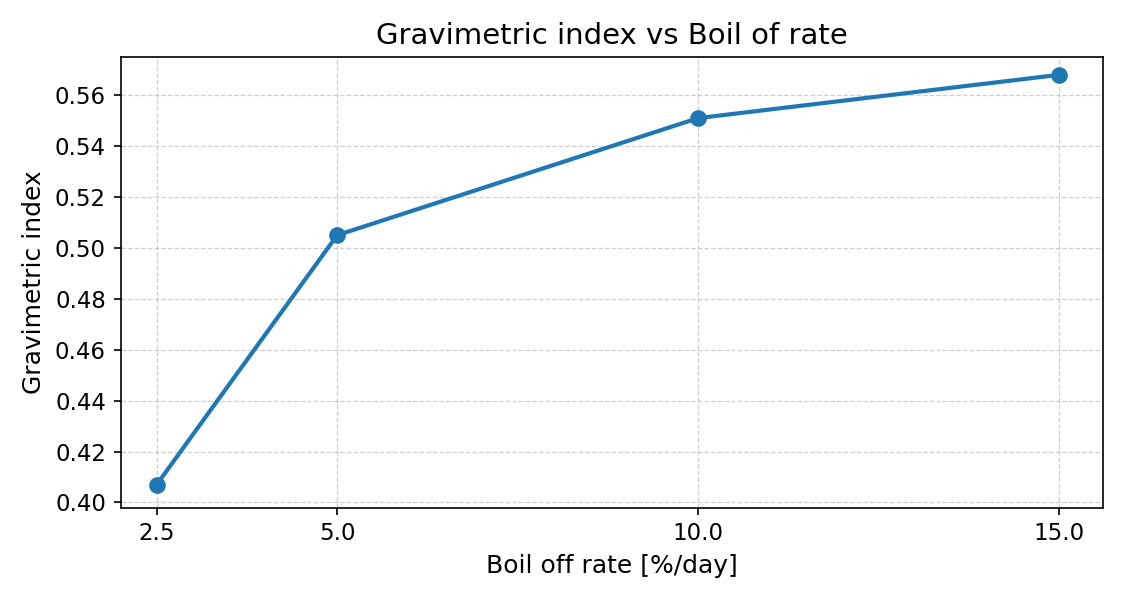
Figure 2. Gravimetric index vs Boil-off rate.
Table 3. LH2 tank characteristics.
Hydrogen is stored in the fuel tanks at an assumed steady pressure of approximately 1.6 bar and is supplied to the distribution system. The inner pipe wall material is selected to maintain mechanical integrity under cryogenic conditions, thereby reducing the likelihood of cracking and leakage. Stainless steel (SS 304), with a density of 8000 kg·m-3, is adopted due to its established performance at temperatures down to approximately 20 K. Closed-cell polyurethane foam is used as pipe insulation because of its low thermal conductivity and low density, which help limit heat ingress while minimizing added mass. The outer pipe layer is modelled as aluminum alloy (Al 2219), selected for its low density and cryogenic suitability, and for providing mechanical protection to the insulation. The selected materials and key properties are summarized in Table 4.
Table 4. Pipe wall layers.
A parametric study is conducted by varying the inner diameter of the tubing from 2 to 7
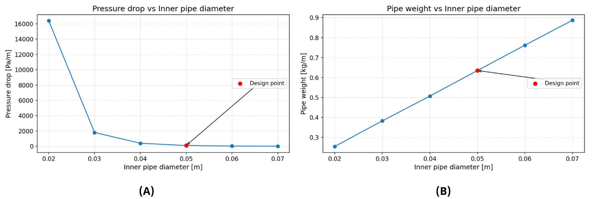
Figure 3. LH2 pipe pressure drop (A) and pipe weight (B) vs inner diameter.
Hydrogen is maintained in the supercritical region to reduce the risk of sudden phase changes in downstream components and to account for temperature variations and possible instrument inaccuracies. Based on this fuel condition, the thermal insulation of the distribution system is modelled. Before entering the engine-mounted pump, hydrogen is expected to reach a temperature of 27 K and a pressure of 13.5
Table 5. LH2 pipe design characteristics.
Six pumps and the associated hydraulic components are selected for the fuel distribution system to ensure effective fuel delivery, with weight data for pumps, valves, and hydraulic elements derived from available literature. The piping system, fully dimensioned with material and geometric considerations, is used to estimate its weight contribution by accounting for the aircraft’s spatial constraints and available path lines incorporating both safety and return lines for the engines and tanks [2,21,22]. The resulting system developed on the COCO simulator platform and its representation regarding the individual tank supply to the engine is presented in Figure 4.
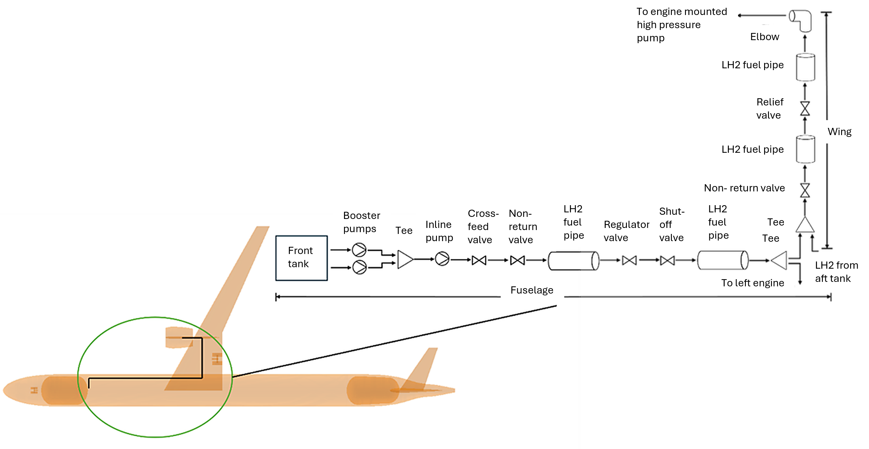
Figure 4. LH2 fuel distribution system aircraft integration.
This work was compared with weight estimation methods presented, where most correlations are based on kerosene fueled architecture. As a result, they showed significant deviation from the weight calculated in-house. In contrast, the Cryoplane study, which is based on hydrogen fuel, predicted a value of similar magnitude to the results of this study, as can be seen in Table 6. The deviation between the empirical correlation–based estimations and the analytical calculation of the system’s weight, considering the studied engine, tank, and fuel configuration, is calculated based on eq. 30 and presented in the table below.
Table 6. LH2 fuel system weight estimation comparison.
where
This study presents a methodology for designing and evaluating a liquid hydrogen fuel system for short-range aircraft applications, demonstrating a coupled conceptual design framework that combines tank sizing with one-dimensional distribution modeling to quantify thermohydraulic behavior and mass drivers. For the storage system, the primary objective is to satisfy allowable boil-off limits while minimizing tank structural mass; the parametric analysis shows that the BOR constraint directly drives the required insulation thickness and, in turn, the overall tank mass and gravimetric efficiency, with a design point BOR of 5 %/day selected as a practical balance between thermal performance and mass penalty for a short-range application. For the fuel distribution system, the focus is on ensuring delivery of hydrogen above the critical pressure at the engine interface, with minimal pressure losses and heat ingress, while maintaining a low overall system mass. Comparison with available literature-based estimates indicates a deviation of approximately 13% in total fuel system weight, with the AUTH model tending to overpredict mass; this provides an initial consistency check for the approach and suggests that the main trends are captured, although further refinement is required. Future work will extend the modeling to supporting subsystems such as refueling/defueling, pressurization and venting, toward a more complete and integrated aircraft level hydrogen system architecture.
Dataset available on request from the authors taking into consideration the Grant Agreement No: 101056863 guidelines.
The research is part of the “Minimal environmental impact ultra-efficient cores for aircraft propulsion” MINIMAL project funded by the European Union’s Horizon Europe research and innovation program under grant agreement No: 101056863.
The authors have declared that no competing interests exist.
Conceptualization: V.K., Z.V. & D.M.; Methodology: V.K., Z.V. & D.M.; Software: V.K., Z.V. & D.M.; Validation: V.K. & K.F.; Formal analysis: V.K., Z.V. & D.M.; Investigation: V.K., K.F., Z.V. & D.M.; Resources: V.K. & K.F.; Data Curation: V.K.; Writing - Original Draft: V.K.; Writing - Review & Editing: V.K., Z.V. & D.M.; Visualization: V.K. & K.F.; Supervision: Z.V. & D.M.; Project administration: K.Y.; Funding acquisition: K.Y.
The following abbreviations are used in this manuscript:
| 1. | Fuel Cells and Hydrogen 2 Joint Undertaking. Hydrogen-powered aviation: A fact-based study of hydrogen technology, economics, and climate impact by 2050. Luxembourg: Publications Office of the European Union; 2020. |
| 2. | Brewer GD. Hydrogen aircraft technology. London: CRC Press; 1991. |
| 3. | Sethi V, Sun X, Nalianda D, Rolt A, Holborn P, Wijesinghe C, et al. Enabling cryogenic hydrogen-based CO2-free air transport. IEEE Electrific Mag. 2022;10(3):24-31. [Google Scholar] [CrossRef] |
| 4. | Xisto C, Lundbladh A. Design and performance of liquid hydrogen fuelled aircraft for year 2050 EIS. Gothenburg: Chalmers University of Technology; 2022. |
| 5. | Federal Aviation Administration. Fuel tank flammability reduction means. Washington (DC): Federal Aviation Administration; 2008. |
| 6. | Ebrahimi A, Rolt A, Jafari S, Huete Anton J. A review on liquid hydrogen fuel systems in aircraft applications for gas turbine engines. Int J Hydrogen Energy. 2024;91:1-24. [Google Scholar] [CrossRef] |
| 7. | Winnefeld C, Kadyk T, Bensmann B, Krewer U, Hanke-Rauschenbach R. Modeling and Designing Cryogenic Hydrogen Tanks for Future Aircraft Applications. Energies. 2018;11(1):105. [Google Scholar] [CrossRef] |
| 8. | Abedi H, Xisto C, Jonsson I, Grönstedt T, Rolt A. Preliminary analysis of compression system integrated heat management concepts using LH2-based parametric gas turbine model. Aerospace. 2022;9(4):216. [Google Scholar] [CrossRef] |
| 9. | Cálão MN. On the Use of Hydrogen as the Future Aviation Fuel. Lisbon, Portugal: Instituto Superior Técnico, Universidade de Lisboa; 2018. |
| 10. | Lampeas G, Tzoumakis G. Thermo-mechanical simulation of a small-scale liquid hydrogen fuel tank for aviation applications. In: Proceedings of the 9th European Conference for Aeronautics and Space Sciences (EUCASS-3AF 2022); 2022 Jun 27–Jul 1; Lille, France; Brussels, Belgium: EUCASS Association; 2022. [CrossRef] |
| 11. | Dannet G. Integration of cryogenic tanks and fuel cells for future hydrogen-powered aircraft. Linköping, Sweden: Linköping University; 2021. . |
| 12. | Verstraete D. The Potential of Liquid Hydrogen for Long Range Aircraft Propulsion. Cranfield, UK: Cranfield University, School of Engineering; 2009. |
| 13. | Mantzaroudis VK, Theotokoglou EE. Computational analysis of liquid hydrogen storage tanks for aircraft applications. Materials. 2023;16:2245. [Google Scholar] [CrossRef] |
| 14. | CAPE-OPEN Laboratories Network. COCO – the CAPE-OPEN to CAPE-OPEN simulator [Internet]. CO-LaN; 2023 [cited 2025 Sep 10]. Available from: http://www.cocosimulator.org/. |
| 15. | CoolProp Development Team. CoolProp: Open-source thermodynamic properties database [Internet]; 2018 [cited 2025 Sep 10]. Available from: http://www.coolprop.org. |
| 16. | White FM. Fluid mechanics. 7th ed. New Delhi: Tata McGraw-Hill Education; 2009. . |
| 17. | Incropera FP, Dewitt DP, Bergman TL, Lavine AS. Fundamentals of heat and mass transfer. Hoboken, NJ: John Wiley & Sons; 2007. |
| 18. | Azimi A. Liquid hydrogen fuel distribution system performance for short medium range civil aircraft. Gothenburg: Chalmers University of Technology; 2022. |
| 19. | Olives F. Weight estimation of parametrically design of fuel and hydraulic systems of a commercial airplane. London: Imperial College of Science; 2019. |
| 20. | Gollnow M. Passenger aircraft towards zero emission with hydrogen and fuel cells. Hamburg: Hamburg University of Applied Sciences; 2022. |
| 21. | Seeckt K. Conceptual design and investigation of hydrogen-fueled regional freighter aircraft. Hamburg: US-AB; 2010. |
| 22. | Airbus Deutschland GmbH. Liquid hydrogen fuelled aircraft – system analysis. Hamburg: Airbus Deutschland GmbH; 2003. |

![]()
Copyright © 2026 Pivot Science Publications Corp. - unless otherwise stated | Terms and Conditions | Privacy Policy


